
// capability 05 · inserts and riveting
Fixings & hardware, fitted in-house.
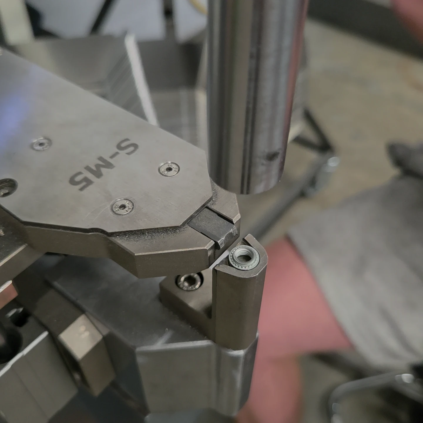
Press-fit inserts, rivet nuts, studs, standoffs and blind rivets add durable fixing and joining points to thin sheet. We plan the hole, access, installation and finish together.
Inserts and captive hardware
The route can include press-fit nuts, studs and standoffs, rivet nuts and other specified captive or threaded hardware. The right choice depends on sheet material and thickness, thread size, access, expected load and whether the fixing must be serviced from one side.
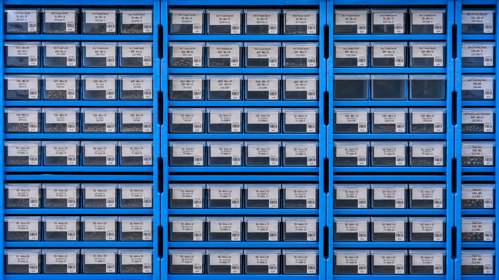
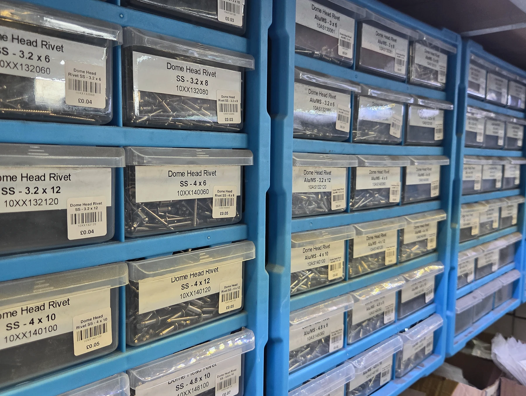
We keep a broad workshop range in clearly identified bins. Where a particular manufacturer or part number is required, include it on the drawing or bill of materials so the correct hole preparation and installation requirement can be used.
Riveting as a joining process
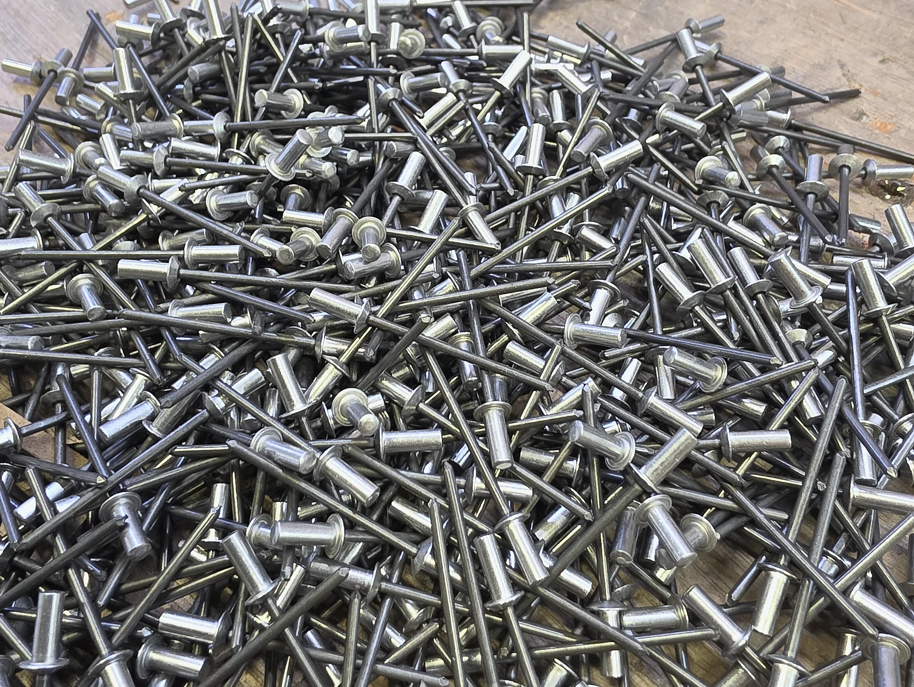
Blind riveting joins sheet-metal components quickly and consistently, especially where access is available from only one side or heat from welding is undesirable. Rivet material, body diameter, head style and grip range must suit the sheets being joined.
Riveting is useful for panels, guards, ducts, enclosures and mixed-material assemblies. We can combine it with tabs, slots and locating features so the parts align before the rivet is set.
Designing for inserts, rivets and hardware
Performance starts with the drawing. Hole size, edge distance, sheet stack, grip range and installation direction are specific to the selected fixing.
Specify the exact hardware
Call out type, thread, length and—where it matters—manufacturer and part number. “M5 insert” or “blind rivet” alone may not define the hole, head, grip range or installation method.
Leave room around the fixing
Keep enough material around the prepared hole and allow access for installation tooling. Check that folds, welds and nearby components do not block insertion or the rivet tool.
Plan the finish sequence
Coating can affect threads, electrical contact points and close fits. State what must be masked and whether each fixing is installed before or after finish.
What to show on the drawing
Identify every fitted item with a leader or hole table, and include the required quantity per part. Show which side receives the head or flange, any projection requirement, and whether the installed hardware controls an assembly dimension.
If pull-out, torque or other performance is critical, provide the application requirement so the hardware can be selected and verified appropriately.
Part of the complete assembly
We cut and form the component with the chosen hardware in mind, fit it at the correct stage, and protect or mask it through welding and finishing as agreed. This keeps responsibility for the finished interface with one team.
Unsure which insert to use? Tell us the sheet material and thickness, thread, access, load and how often it will be assembled. We can discuss a practical route before quoting.
Send the drawing and hardware requirement
Include the part file, sheet specification, fixing call-outs, quantity and final finish. We will check the installation sequence with the rest of the fabrication route.