
// capability 03 · flexible, repeatable forming
Repeatable folds, planned before we cut.
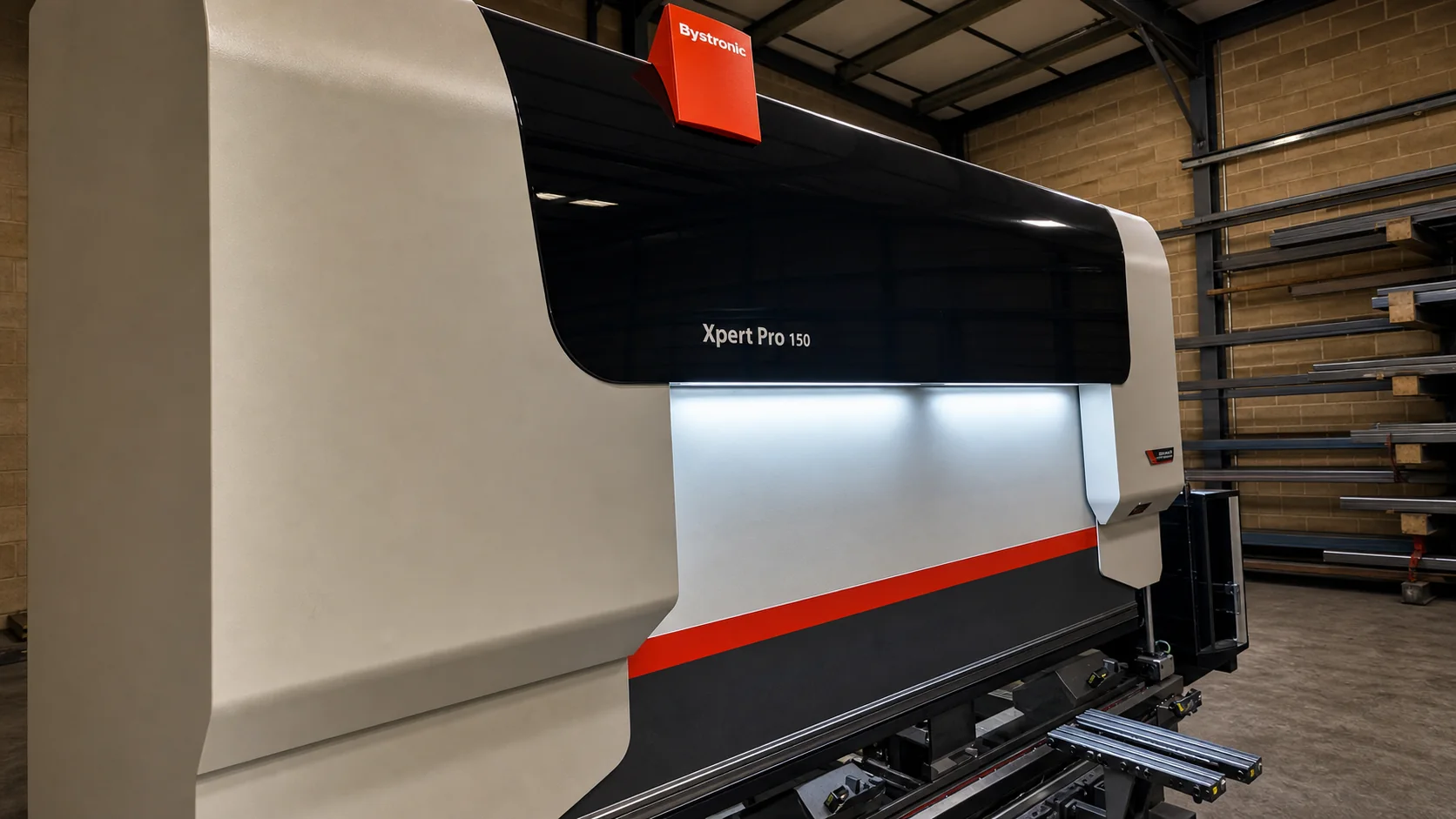
Three top-spec Bystronic press brakes cover flexible, operator-led bending from one-offs to production runs. One robotic cell adds efficient handling only for suitable high-volume repeat parts.
What we offer
We form mild steel, stainless and aluminium parts on three top-spec Bystronic press brakes as part of one connected fabrication route. Typical work includes angles, channels, trays, guards, covers, brackets, panels, chassis and enclosures, from a first prototype through to repeat batches.
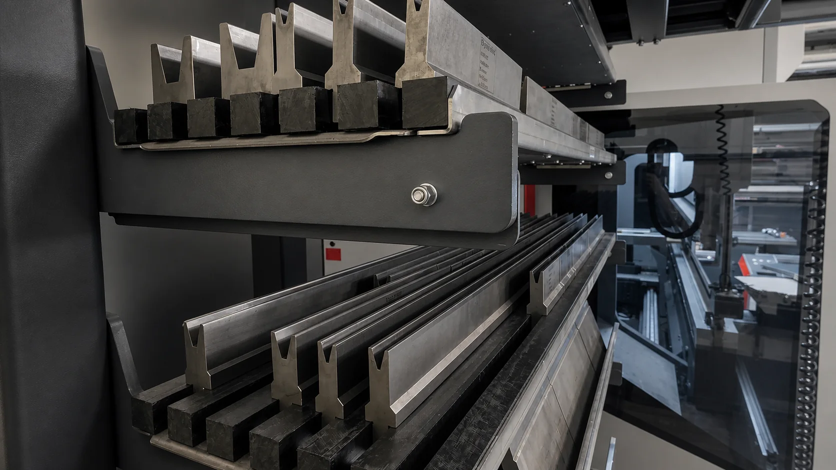
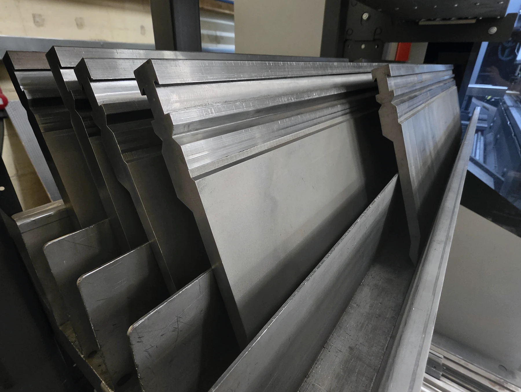
Experienced operators select the tooling and sequence for the part in front of them. Work can then move directly to secondary machining, fitted hardware, welding and finish without losing the drawing intent between suppliers.
Why choose press-brake bending?
Press-brake forming is flexible: it can prove a one-off, respond to design changes and repeat controlled folds across a production run. A formed feature can replace a welded joint, stiffen a panel or turn several flat pieces into one simpler component.
For suitable stable, high-volume repeat parts, our single robotic cell can automate handling. It complements the three operator-led presses; it is not the default route for every job.
Designing parts for press-brake bending
The material, thickness, internal radius, flange size and nearby features all interact. We check them as a system rather than treating the flat pattern as finished.
Use consistent radii where possible
Common internal radii and bend conventions reduce tool changes and make results easier to repeat. Avoid specifying a sharp internal corner where the material and tooling naturally create a radius.
Keep features clear of the bend zone
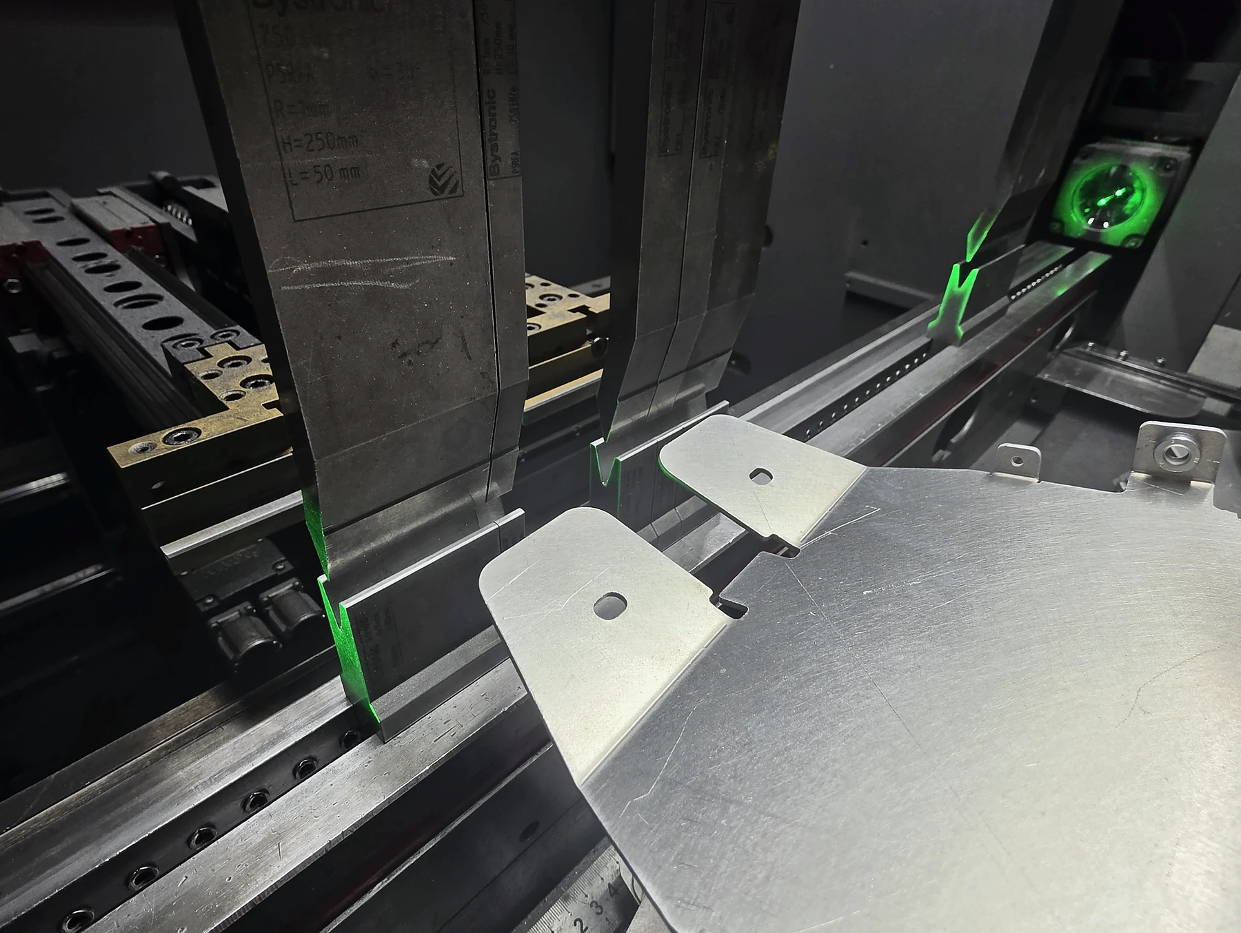
Holes, slots and cut-outs close to a fold can stretch or distort. Move them clear when function allows, or flag them as critical so the route can be reviewed.
Add relief and allow tool access
Bend reliefs can prevent tearing or unwanted deformation at corners. Deep returns and closed shapes also need a feasible sequence and physical access for the tooling.
Dimension the finished form
For folded parts, a STEP model plus a PDF drawing is the clearest combination. Dimension the finished component and identify critical overall sizes, hole positions, angles and datums. Avoid over-constraining every intermediate edge if only the assembled result matters.
The flat pattern should use the bend allowance agreed for the actual material and route. If you are unsure, send the folded model and let us create or verify the developed blank.
Think about what follows
Specify which faces will be visible, where inserts or welds will sit, and whether the part will be powder coated. Access for hardware and joining can change the best fold sequence, while coating adds thickness around close fits.
Prototype before volume. For a new or tolerance-sensitive design, a first-off part is the most useful way to confirm fit and function before a larger batch.
From folded part to finished assembly
Bending is one stage of the route. Keep moving through the guides or send the complete requirement and let us plan it as one job.
Send the folded model and drawing
Include material, thickness, quantity, finish and the dimensions that control fit. We will review the form before confirming the route.